RV-9A: Forward Section - 3/9/2009
Home Previous Entry Next Entry Back |
Share on:

|
|
 Time to drill the bottom holes in the pedal horns to attach the master cylinders Time to drill the bottom holes in the pedal horns to attach the master cylinders
After visiting Matt and Melissas RV-7A website, I decided that their method for attaching the master cylinders pretty dang slick. So I'm doing mine the same way. Here have a file with a paint stirring stick (cut up) behind it clamped to the pedals. This should set the pedals far back enough to where I won't be hitting the breaks while using the rudder.
|
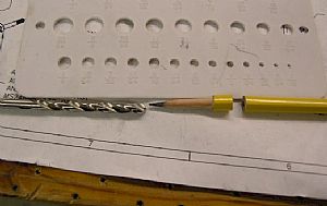 Now make the mark on the pedal horn for the hole Now make the mark on the pedal horn for the hole
I got a 3/16" drill bit and my hole size checker and started whittling a sharpened pencil down to size using my scotchbrite wheel, while twirling the pencel between my fingers. I whittled it down until it fit tightly inside the 3/16" hole in my plastic hole size checker.
|
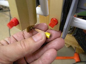 Making the mark Making the mark
This was the easy part. With the cylinder already attached on top, I stuck the pencil through the bottom cylinder hole and swung it back and forth, making a mark on the pedal horn.
|
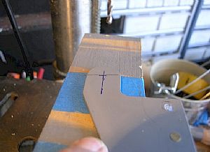 Now to drill the holes in the pedal horns Now to drill the holes in the pedal horns
Originally I had marked a spot (in blue) where I thought the holes would be. The pencil mark shows where the hole will actually be. The funny part about this is that on the left pedal, the pencil mark is above my projected blue mark and the right pedal is the same distance below the blue mark. I like it!
|
 Bolted on the master cylinders Bolted on the master cylinders
Both pedals are now perfectly in line with each other.
|
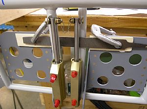
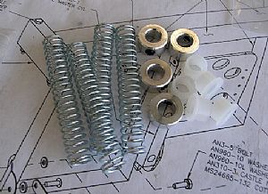 Time for the springs. Time for the springs.
I had read on Vans Air Force where people were opting to put these springs on their master cylinders to insure the pedals would spring back after they are depressed. Actually most people spring back after being depressed! These parts are available at McMaster.com. Just do a search on these part numbers:
6389K625 - 1 Pack Nylon Bearing, Flanged, For 3/8" Shaft Dia, 1/2" Od, 3/8" Length
9657K115 - 1 Pack Steel Compression Spring, Znc-pltd Spring-tempered, 3" L, 1/2" Od, .047" Dia
9946K13 - 4 Each Aluminum Set Screw Shaft Collar, 3/8" Bore, 3/4" Outside Diameter, 3/8" Width
|
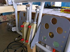 Done! Done!
Kinda' cool looking too! Don't ya' think?
|
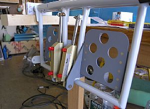
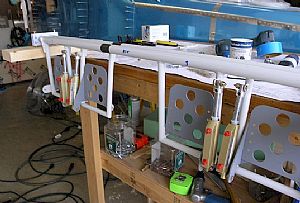 The big picture The big picture
All the pedals are done!
|
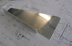 Trimed and drilled the F-6118 Rudder Pedal Brace Trimed and drilled the F-6118 Rudder Pedal Brace
The instructions mention trimming the brace to allow room for the F6O1K Firewall Recess, so clecoed the recess back in place on the firewall to get a better picture of what they are talking about. I used a combination of the bandsaw and the scotchbrite wheel to trim the part. I also pre-drilled the holes as indicated by the drawing.
|
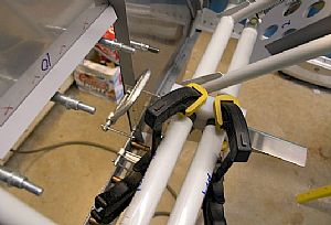 Clamped the F-6118 brace into position Clamped the F-6118 brace into position
I clamped the center bearing blocks first to establish the position where the brace will get final drilled into the F-601 upright firewall stiffener. Then I clamped the brace to the firewall stiffener. The brace actually goes on the other side of the firewall stiffener, but drilling on this side makes this whole process easier. I all have to do is transfer the brace to the other side of the firewall stiffener after this drilling is done.
|
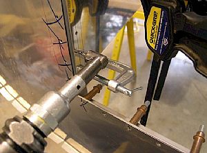
 View of the clamped brace from in front of the firewall View of the clamped brace from in front of the firewall
|
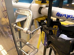
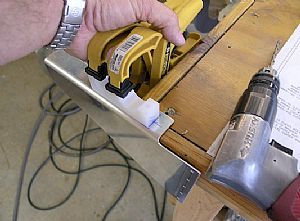
 Time to drill Time to drill
I am so glad that I bought this second hand pneumatic angle drill. I don't use it often, but when I need it, I REALLY need it.
|
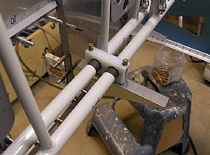
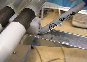 Time to drill the holes in the brace for the bearing blocks Time to drill the holes in the brace for the bearing blocks
I moved the F-6118 rudder pedal brace over on the other side of the F-601 upright firewall stiffener and clecoed it into position. Here I am marking where the bearing block will be with my fine point sharpie.
|
 Drilling the brace Drilling the brace
Even with 2 clamps on the bearing block, that dude still wants to slide around. So, using the bearing block as a drill guide, I drilled the holes into the brace, adding additional pressure with my fingers to keep the block from sliding out of position.
|
 Done! Done!
Boy, I'm glad that finished. Now on to other schtuff!
|
Home Previous Entry Next Entry Back
|